Interferometric Testing Using a Modified Offner Null
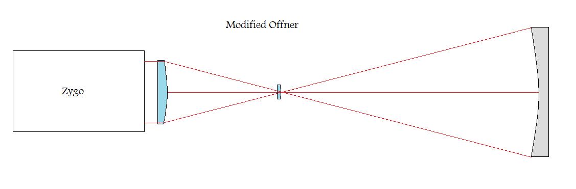
Commercial interferometers like the Zygo or Wyko etc. have an internal collimator which outputs parallel light into either a transmission flat for testing flat surfaces or a transmission sphere for testing spheres. If you want to test paraboloids on these interferometers one method would be to use a transmission sphere and use the Ross null but transmission spheres are rather expensive items. The method I describe here is a modification of the Offner null which consists of two lenses, a compensator or null lens and a weak field lens. Malacara describes the Offner null in Optical Shop Testing in 12.4.1. The null lens is used at conjugates with the field lens near the intermediate conjugate (see below).

This field lens balances out both third and fifth order spherical aberration resulting in highly corrected wavefronts with very low residual error without using large null optics. The null lens actually works with one focal length mirror without the field lens but since I’ll test many different focal lengths I can change the field lens spacing for different focal lengths. Sometimes this causes a larger center area of the field lens to be used than I would like but then I can pick from a couple of different focal length field lenses to remedy this.
Since commercial interferometers already have collimated light output you can simply make the first conjugate of the Offner null lens at infinity. So to set up this test you could use a transmission flat, a null lens and field lens. An even better solution is to use a plano-convex null lens and eliminate the transmission flat. The flat on the null lens must be polished free of irregularity and becomes the reference surface for the interference cavity. This then means you only need two lenses for this test.
Test Apparatus
My interferometer is a Zygo GH, the first commercial Fizeau interferometer made by Zygo around 1975 (picked up surplus and is now a collectors item). The null lens I use is a surplus coated plano-convex lens with a 13.79 inch radius made of Bak5. The curve side was 1/10 wave over about 3 inches as tested on an interferometer but the plano wasn’t good enough. In any case the coating needed to be removed because it’s a reference surface and I polished it free of irregularity checking it on a master flat. It only needs to be free of irregularity and not absolutely flat, (it can have several rings of power). I edged this lens free of wedge to fit in a bayonet lens cell that fit’s on my interferometer holding the lens in a stress free state. This lens is about the minimum focal length lens I would recommend because at F/5 it uses only 2.28 inches of the 4 inch beam of the interferometer. If you use a shorter focal length then the image size on the interferometer becomes too small. At F/3 you will use about 3.6 inches and less for a slower mirror but I found this to be a good overall lens for most amateur telescope mirrors. The clear aperture of the reference/null lens must be less than 4 inches. Or you will clip the edge of your mirror
I marked a small X at the very center of the lens with a felt tip pin checking it with calipers. The 2 inch diameter plano-convex field lens is from Newport Optics and is one I had laying around with about a 6 inch radius. You only use a small area in the middle so it’s more than likely good but doesn’t hurt to check it. Actually this isn’t the idea lens, it has a residual error of about 1/100 wave testing a 12 inch F/5 parabola. A one meter focal length lens would give me 10 times less error, but I’m already ten times better than the reference surfaces are certified to be. This will be more important in testing a large fast mirror.
I mounted the field lens in a simple tip/tilt and X-Y mount and mounted on a piece of extruded aluminum held on a board with Teflon clips. This lens bench slides smoothly with about 5.5 inches of travel. By the way the field lens must be AR coated or you can get extra unwanted fringes from it.
With interferometric testing mirrors it’s almost impossible to do any testing without a motorized X-Y-Z holder for the mirror. On my test stand I used inexpensive low RPM gearmotors to drive fine pitch Newport actuators on the X-Y and a piece of 10/24 brass threaded rod again driven by a low RPM DC gearmotor on the Z. These are wired into a box with toggle switches for easy use.
Testing
The reference flat/ null lens is put on the interferometer and aligned like a transmission sphere or flat. This is a big advantage because it guarantees the lens is properly aligned for testing. Next the mirror to be tested is put on the test stand at the right radius distance and adjusted so that the shadow of the X on the null lens is at the center of the mirror. This insures that the mirror is on the axis of the null lens. Next the field lens is placed in line near the focal point of the null lens and centered in the beam. If you take the reference/null lens off the interferometer you can get a reflection from the flat side of the field lens (flat side must face the interferometer) and align it square to the interferometer with its tip/tilt mount. Remount the reference/null lens on the interferometer. Next move the field lens so that its flat side is at the focus of the reference/null. There is a lot of spherical aberration but you want to find the spot where the paraxial rays focus on this surface. The fringes will be straight on center but curve outside the paraxial area (forming a capital letter D). If the coating is very good these fringes may be faint and hard to see. This is the cat’s-eye position and where you should zero your digital calipers. Based on the ray trace data for the null lenses and mirror you are testing you move the field lens toward or away from this spot. I hope this doesn’t sound complicated, it’s really very easy. This is the only airspace you have to set and the tolerance is rather loose. The mirror on the test stand is then aligned to the interferometer using the XYZ adjustments. Switch to alignment mode and remove any power fringes with the Z focus. I mark my toggle switch to tell me if I’m going short or long on the radius to help interpret the fringes visually. There may be some residual coma present due to the centering of the field lens ( the only adjustment left) and you can tweak the X-Y knobs on the field lens to remove coma. You can’t mark the center of the field lens because the area used on the field lens is often very small.
I refigured an old 12 inch F/5 telescope mirror I had just to prove that the method works. I was absolutely thrilled with it’s performance. I actually tried both the Ross and Offner on my 12 inch mirror and found that the Offner was much easier to properly align. I was never certain that I had correct alignmnet or a warped mirror with the Ross null and I don’t want to lose this important advantage of interferometry.
This test may not be for everyone but I think it is unbeatable for testing telescope mirrors with standard interferometers. I especially like the ability to work in two dimensions. Astigmatism is a more common defect than amateurs realize and interferometry is the only method that gives you two dimensional information.
Open Fringe
Since my interferometer doesn’t have phase-shift capabilities I use Open Fringe which can be down loaded from Yahoo’s interferometry group site. This is a really neat program that can measure a static interferogram and give you a two dimensional and cross-sectional plot of your mirror. It can average the Zernikes from several different maps for a better measurement of your mirror. The following is a report on a mirror I did measured by Open Fringe .

