Making and Testing an Auto-collimating Flat Auto collimation is a test method using a full size flat mirror to test parabolic mirrors and telescopes in double pass using a light source at the focus of the optic. It is a null test and very quick, once correctly aligned, not needing zonal reading or analysis. The only problem is that a large flat is quite expensive and hard to find. Making a large flat is also problematic since you need another large flat to test against for contact testing. However an autocollimating flat doesn’t need to be as absolutely flat (as a diagonal mirror should) but can have some “slight” amount of power.
So how flat does it really need to be? The answer depends on:
- The size of the mirror
- The speed of the mirror
- The allowable residual error
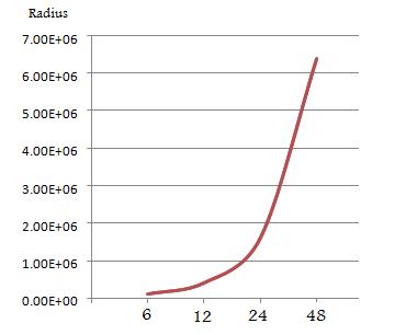
The fastest mirrors have the most residual error so the worst case scenario would be a mirror the same size as the flat and about f/2.5 (about the fastest ATM mirror). So if I want to be very conservative and say the maximum allowable error should be <= 1/100 wave for mirrors slower than f/2.5 then we will have the plot below as a radius of curvature in inches for our flat:
In an article in Sky and Telescope July 1990 I described the Raleigh water test for flats and that a collimating lens is required for the test. This is to avoid a cosine error coming from the light traveling through the thickness of water which causes a false number of rings of power when viewed from a close distance making it difficult to measure the true flatness. Again these false fringes come from both the viewing distance and the water thickness causing light at the edge to travel a longer distance than light traveling through the center of the water layer. However if our flat has just the right amount of concavity the water path length is shortened at the edge to where it matches the path length in the center and then the fringes will appear straight! This is useful because now we can analyze a large “near” flat without a collimating lens (one of the biggest disadvantages of the Raleigh water test) providing we know both the water thickness and the viewing distance which we can measure. There are limits to this, however, because if the “flat” radius is too short or the water thickness too large too many fringes are created and the resultant compensated fringes will no longer be straight but are S shaped with residual spherical aberration. However this residual error can be kept small enough to be insignificant if the radius on our flat is no shorter than those in the graph above.
Practical aspects:
We must be able to measure 2 things: water thickness and viewing distance. Viewing distance ought to easy, especially if the light path is not folded: just measure the distance from the flat to the camera lens. Some light boxes use a folded light path so you must figure out the distance from the camera lens to the fold and to the flat. If you are going to try to measure true flatness I wouldn’t recommend a folded light path. A fraction of an inch change in viewing distance can make a noticeable change in the number of fringes.
Measuring water thickness can be done simply with the micrometer fixture in this photo. The micrometer is zeroed on a flat surface and then back out. The fixture is then placed on the flat covered in water and the micrometer slowly advanced. When the ball tip touches water the capillary attraction is easily seen and the micrometer distance is noted.
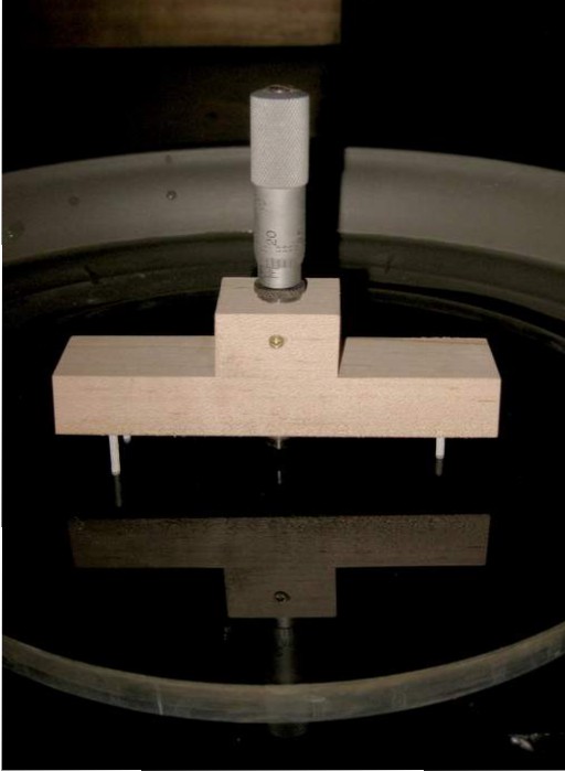
| This fixture is just a maple block with a hole drilled to fit a micrometer. Three aluminum nails are used as feet with the ends rounded off with a file. The micrometer has a ball tip and is zeroed on a known flat surface. |
|
Changing either the water thickness or the viewing distance will change the number of false fringes but I have found the water test works best with about 1 millimeter of water. For simplicity then I will use a constant water thickness of one mm a using 546 nm light source.
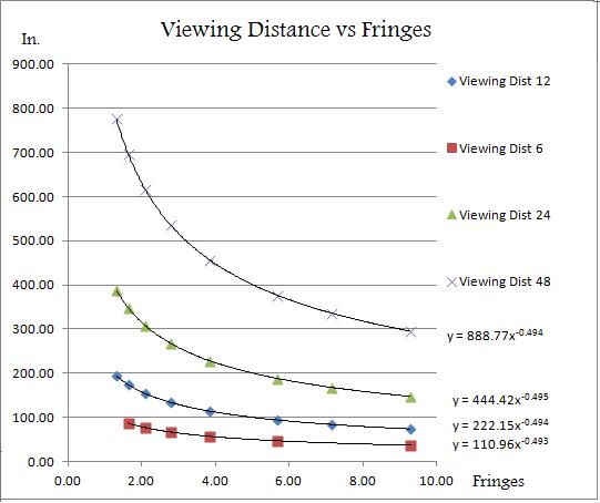
The graphs above allow you to test an autocollimation flat without using a collimating lens eliminating the biggest disadvantage of the water test. It can lead to a long viewing distance especially for large diameter flats but this is a minor problem compared to trying to find a large diameter collimating lens. You can also change the viewing distance somewhat if the radius of your flat changes provided you keep you keep under 6 to 10 fringes which is about 1/100 to 1/50 wave. This makes it easier to fabricate than a master optical flat. Regardless of the mirror size the number of fringes visible depends on the sag. as shown in this graph:
Two microns or less is not very much sag. but this is because the fringes arise in the water and don’t forget each fringe is only 3/8 wave surface error. A nearly full size spherometer is needed with a sensitive indicator. Some indicators can measure down to ½ micron sensitivity (Mahr). You could zero your spherometer on the grinding tool to double the sensitivity but be sure both pieces are not aspheric. You can always just grind both tool and mirror flat and simply polish the slight concavity with the mirror on top quite easily.
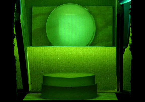
A monochromatic light box used for contact testing of flats can also work for water testing consisting of fluorescent mercury lamps with a green filter. Bug zapper bulbs are readily available and not too expensive and use a green plastic to filter out the green line.
|
When using a lighbox with a diagonal be sure to measure the distance to the diagonal and the folded distance.
Going Further
Using this idea it is possible with current freeware fringe analysis software to analyze an interferogram taken of a optical flat using the water test without a collimator to determine if it is truly flat. To do this you would determine the fringe number from the graph (interpolating other diameter mirrors using the curve equations). You would need to measure accurately your viewing distance and water thickness; an unfolded lightbox is preferable. For analysis you would shoot an interferogram and verify that the surface appears convex (it could also be concave with the same number of fringes so you must verify that it appears to be convex and not concave; see water testing procedure). I haven’t worked a flat larger than 12 inches because I haven’t needed an autocollimation test flat but I have verified that I the computation for the number of fringes matches the number actually seen. I used Zemax to compute these graphs but perhaps the computations could be done on free optical programs such as OSLO edu.
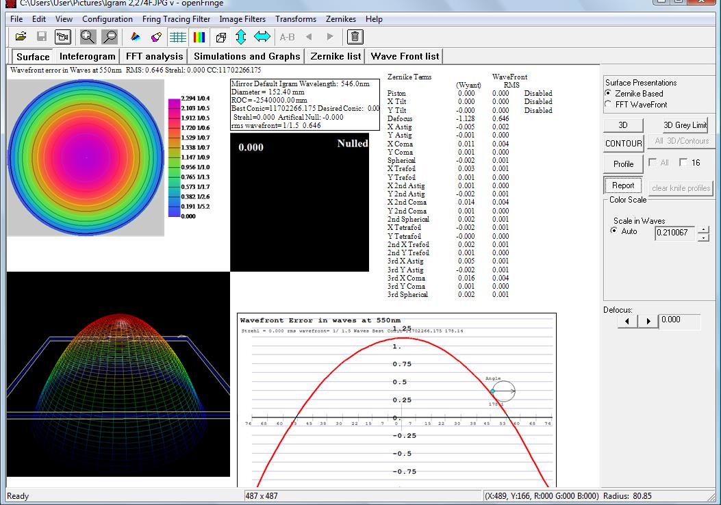
In a fringe analysis program such as Open Fringe you would change the Zernike 3rd term which is the power term to a value half the number of computed fringes. Here is an example of an interferogram with 2.27 fringes of power analyzed in Open Fringe. You should click off
defocus in the Zernike table or it will be subtracted out automatically. This report is not of much use unless you can subtract a Zernike file of a true flat that has the number of fringes for the viewing distance and water thickness you measure. Lacking this Zernike file you can just look at the defocus value in the Zernike table. If your Interferogram is convex but is displayed as concave click the invert wavefront button. The interferogram analyzed in this example had 2.27 fringes of power and its Zernike defocus value is -1.128, very close to ½ the fringe value. You should work the flat until the defocus value is as close to ½ the calculated value as possible but again be careful of the +/- convex/concave sign convention. The longest viewing distance gives the fewest fringes and least error sensitivity to errors in the water thickness.
Ed Jones
