Making an Equatorial Platform
Your Dob isn’t really complete until you’ve made an equatorial platform to go with it. It is so much nicer not to have to continually nudge your scope around especially at high power and making a platform is remarkably simple. The equatorial platform is merely a section of a cone whose axis is aligned with the north celestial pole and the COG of the telescope is on this axis. The platform bearings are sections of this cone. You can make a platform with only one bearing and a pivot but a 2 bearing platform is more compact. There are many good sources on the internet for how to make a platform but I will describe how I build mine. I don’t think I’ve ever made 2 exactly the same but the method doesn’t change.
Determine the COG: You must first calculate the COG of both the telescope & rocker box and the moving part of the platform. If not the telescope may want to tip over or drive poorly. It doesn’t need absolute accuracy but then it shouldn’t be ignored. First you need to weigh each component and measure each distance from the floor. The scope OTA is easy; you just measure to the center of the alt bearings. The rocker box is weighed and balanced on its side using a wooden dowel. Measure the distance from the balance point to the floor. You don’t know the weight of the platform since it isn’t built but you can estimate it by weighing a square of plywood that your ground board sits on comfortably (probably ¾ inch). Now calculate the torque:
Torque= (OTA height –X)*OTA weight + (rocker height-X)*rocker weight + (platform height –X)* platform weight
(platform height is a negative number) Do this on a spreadsheet and change the value of X until the torque is zero and then X is the COG height above the floor. Next you need a board for the platform wide enough for the ground board feet to sit on plus a distance roughly Rn/4 to allow an hour of travel. The front edge of the platform is curved forward to allow the placement of triangular pieces to brace the north bearing. You then make a side view drawing of the platform with the COG centered over the center point of the ground board feet and determine the length of the north and south bearings. Given you latitude and COG you can do this full scale on paper or do the trig calculations and determine the radius of the north and south bearings. The width of the north bearing determine the cord length of the north bearing which must be at least as wide as the platform (but could be truncated):
width > = Radius-sqrt(radius^2- (cord/2)^2)
The radii of both bearings are determined from an AutoCad or paper drawing.
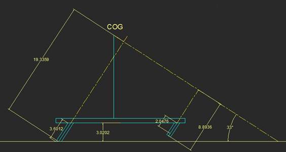
Typical platform side view showing placement of COG
For the top board layout you should dray a circle where the ground board feet go (or if you want to replace the ground board with Teflon pads). The width of the top board must be wider than this circle because you need 1/2 hours worth of travel on each side of the two front pads. Ideally you want the two front shafts directly under the two front pads when level for the most stable platform. The south bearing should also be under the south pad as close as possible. The profile of the top board is fairly arbitrary.
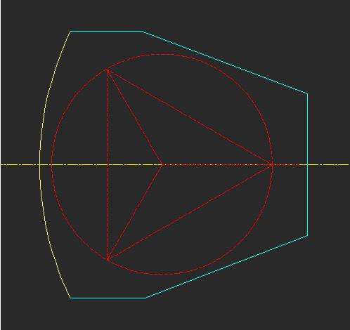
Typical top board layout
Motor Types: I like a direct drive for its simplicity where the north bearing rides on a steel shaft driven by a motor. Some prefer stepper motors but they can produce vibrations if not driven with enough speed so I like synchronous motors which are inexpensive and always quiet. Synchronous motors are available in specific speeds and so you must match the motor speed and drive shaft diameter to the north radius. I also am a firm believer in using two motors because synchronous motors aren’t expensive and allows you to use the platform for virtually any telescope that will fit without as much concern for the COG. One drive motor can slip if you violate the COG placement very much.
North radius = (1436/ (60/motor rph) * shaft diameter)/2
Example: a 4 rph motor with .5 inch shaft needs a 23.93 inch north radius. You could machine the shaft diameter to an exact calculated amount but it is simpler to use standardized shafting and if necessary adjust the north radius slightly by shifting it forwards or backwards a little. Steppers are simply run at the appropriate speed but you should do the calculations so that they run at least 25 steps/second to minimize vibrations.
Bearing Construction: I prefer to make a conical north bearing (at an angle perpendicular to the rotation axis) rather than the vertical north section (VNS) bearing because the VNS curve is an ellipse and the fixturing is more complicated. Both work fine but I like simplicity and a conical bearing is simpler and just as rigid. The bearings are easily made on a table saw with a sanding disk. I start by tilting the table saw blade to my latitude angle and running the boards used for the bearings. Next I tack on a scrap piece of ¼ inch plywood to the back of the north bearing using brads (temporary). I draw a radius about an inch longer than the required north bearing to the right width and length of the north bearing chord (using a stick compass, be sure to mark the COC of the radius you draw). I then cut the curve on a band saw. Next I bolt on a piece of wood (extension) using the large surface holes on my table saw. This gives me room for any length radius and lets me use a hammer to tap this piece closer to the saw shortening the radius. I tilt the saw blade to my latitude and drive a nail through the COC mark into this wood close to the saw blade. The saw blade is raised only 1/8 inch at a time and the bearing is pushed slowly into (never the other way!) the saw blade pivoting on this nail. This is repeated raising the saw blade only 1/8 inch each pass. Eventually the conical shape is roughed in. The saw blade is raised and then replaced with a sanding disk starting with coarse. Again the bearing is pushed into the sanding disk. I now tap the extension piece with a hammer to shorten the radius as needed; measure from the pivot nail to the middle of the bevel. After finishing with a fine disk the scrap piece is removed. This method gives a very precise, smooth conical bearing. The south bearing is done similarly but is simpler because there is no roughing step (edge is at 90 deg.) It’s helpful but not required necessary to cover surfaces with laminate.

A sanding disk on a table saw gives a very smooth accurate curve
Assembly: The next step is to mark the centerline of each finished bearing. A construction centerline is drawn down the center of the back of the platform with a carpenter’s square and a perpendicular line is drawn for each bearing at the calculated distance between bearings. Each bearing is glued and screwed to the platform with the center marks on the centerline of the platform. Several small triangles of wood with an angle of 90-latitude are glued under each bearing gives it plenty of rigidity.
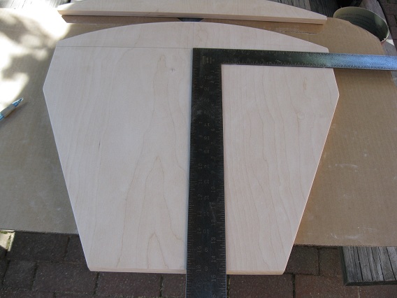
perpendicular and parallel construction lines center point of north bearing attached on line
Ground Board: The ground board can be another board the same dimensions as the platform top or an A frame from hardwood boards. The motors are mounted so that the drive shafts are directly under the feet of the telescope ground board (or Teflon pads if you don’t use the ground board) for rigidity. A center 1/8 inch hole was drilled in the stainless steel shafts plus a small hole for a set screw for the motor shaft. For the pillow blocks I clamped 2 blocks of Teflon or Delrin in a vice and then drilled a ½ inch hole on the split line. The shafts should be smooth to simplify resetting; you just slide the platform back to the start. Most synchronous motors rotate clockwise and so the motors must go in front of the north bearing for the platform to drive in the right direction. If you would find a counterclockwise motor it must go behind the north bearing. The drive shafts are mounted perpendicular to the edge of the north bearing and so point back to the point of the imaginary cone. 2 ball bearings (¼ inch I.D.) are mounted on a block angled (90-lattitude) and 1 or 2 bearings must be mounted on the other side for necessary support. I put a foot under each shaft for a ground pad and added a bolt(s) for leveling in the rear.

Making the Delrin pillow blocks

Clockwise AC motors go in front, place triangle braces under both bearings
The telescope ground board feet, motor shafts and platform feet should all be above each other in a vertical line. The AC motors can be powered by regular house current or by using a small inverter running off a 12 volt battery. Synchronous motors have an accurate constant speed but for astrophotography the speed can be varied by changing the line frequency. I modify a regular inverter by changing the resistance in the RC timing circuit which is rather simple to do.
Worm Sector Drive Tangent drives are popular because it gives a lot of speed reduction for using DC motors but are often problematic because of the linkages. When I figured out how to make worm gear sectors out of Delrin I converted my platform to a worm sector drive since I could mount the worm sector drive behind the north bearing and make a neater looking platform. I bought a long ¼-20 tap on Ebay and made a fixture to hold the Delrin strip while turning the tap with a hand drill. This worm gear sector is long enough to give one hour of tracking. An 8 inch long piece of threaded SS rod was polished with some Scotchbright and mounted on a hinged board with a DC motor and ball bearing on the ends. Springs push the threaded rod into the worm gear sector for tracking but with a lever to allow it to disengage for quick resetting. Powered by inexpensive PWM circuit I can easily set the motor to the siderial rate. I’ve also set it to half the solar rate and used a solar projector on the platform to keep the solar image stationary.
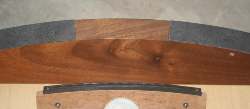
A Delrin worm gear sector
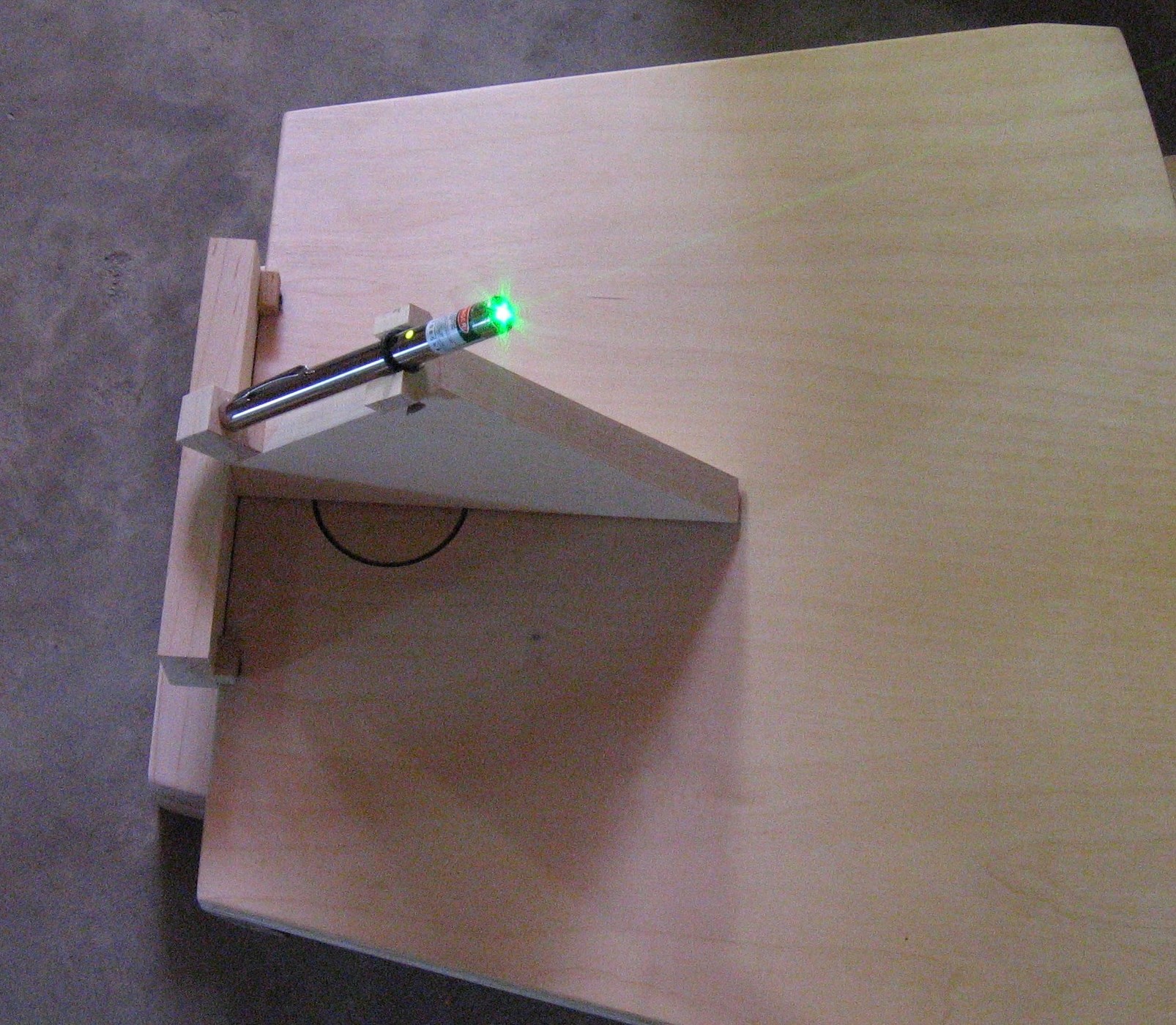
Alignment in Use To use the platform the virtual polar axis must be aligned with the North Pole. Some will do this with a level and accurate compass mounted on the ground board. Another method I like is to make a holder for a green laser. It holds it at the platforms latitude (referencing off the back edge of the platform) and then just put on Polaris.
Sources
AC Motors: Herbach and Rademan
DC Motors: Ebay
Stainless Steel Rod: Speedy Metals
PWM circuits: Bankoktoshop.com
Delrin: McMaster-Carr
Ball Bearings: Ebay
Watch my You Tube video on making a platform: https://www.youtube.com/user/opticsed
