A barn door camera tracker or also known as a Scotch mount is a very simple mount to put on a camera tripod for taking sky photography with an ordinary camera. They are basically two pieces of wood connected by hinges which are aligned to the polar axis. One board is mounted on a camera tripod and a camera is mounted on the other with some means of lifting the board thereby tracking the stars. These can be very simple with a simple manual operation where a nut is turned by hand every so many seconds or with motor drive to set it and forget it. These have also been driven in a variety of ways such as a simple tangent drive which suffers from an inconsistent tracking rate, a double arm drive which approximates a constant rate using two hinges and the curve bolt drive which has a constant rate and is quickly reset. I have made a number of these over the years but when I went to find the latest one I tore my house apart looking for it, it was nowhere to be found. My wife denies throwing it away. Oh well it didn’t cost much to build so I guess it’s time to make another one, I’d hate to not have one in case a nice comet comes around.
If you don’t want to use a motor you need to compute the bolt radius for a 1 rpm gearnut. You make a white disk with a threaded insert in the center marked with 20 divisions. Mount a red LED near the gearnut so you can see the divisions in the dark and an inexpensive watch reading seconds mounted nearby as well. You simply turn the disk every 5 seconds one mark. A 50 mm lens will tolerate an every 15 second interval.
My Junk Drawer
I’m going to motorize this one, forget manually turning a knob every so many seconds, I don’t have the patients I guess, some don’t mind doing this by hand. I looked through my collection of gears and motors (Of course I’m going to spend as little as possible on this one) for a suitable combination.
I wanted the gear nut to turn somewhere around 1 to 1.5 rpm. I found a 10 rpm timing motor with a 10 tooth spur gear and a 65 tooth mating gear giving 1.538 rpm, close enough! If I use a 32 thread per in. threaded rod that gives: 1436 min/day * (10/65 teeth * 10 rpm) / 32 tpi / 3.1416 /2 = 10.988 inch radius required for the curve bolt. I prefer a timing motor because it has less vibration than a stepper even though it runs off 110 volts AC. I’ll just use an inexpensive inverter that I have that cost only $20.
So then I cut out two triangles out of scrap plywood 12 inches wide and 10.5 inches at the base. I sanded them and put two coats of polyurethane on them for dew protection. Then it occurred to me to check the motor to be sure it turned in the right direction. It was clockwise, rats! It needed to be counterclockwise because the gearnut should turn clockwise lifting the barn door. You might say just use it on the other side but then the gearnut will be letting the door drop down by gravity, not preferable even though gravity is very dependable.
Plan B
Ok back to my junk drawer. I can’t find another suitable gear and timing motor combination. I could always buy a timing motor at Herback and Rademan for about $19 but then I’d have to wait for it, try to find a gear combination to work with it and so on. So looking through my junk I found a surplus stepper I bought years ago plus a drive circuit. I had a 16 tooth spur gear for it and a 64 tooth mating gear. Although I prefer a timing motor a stepper motor is reversible and speed is not an issue as long as you don’t exceed a maximum speed. This one is a bipolar gearmotor, probably out of a disk drive. You can buy a bipolar drive from All Electronics Corp. for $25. If you find a unipolar stepper WZ Micro sells a drive for only $10. Mine runs off 4 D cell batteries which is more convenient than AC.
Construction
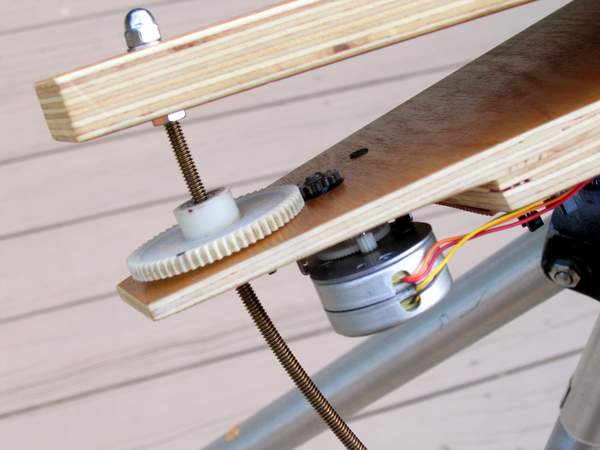
So I have a motor, gears, a brass threaded rod and couple of wood triangles. The shaft on the motor should be long enough for the spur gear to protrude through the bottom board, of course mine isn’t. To remedy this I made a relief cut on the bottom board for the motor.
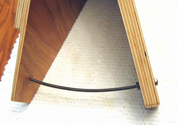
Piano hinge is probably the best hinge but they only sold 6 foot pieces at my local hardware. Instead I bought good quality brass hinges. Don’t use hinges with a sloppy fit! Next I assembled the two triangles and hinges. A long baseline between hinges is desirable
Bending the bolt:
Some seem to have trouble with this but it is actually rather easy to do. I prefer to use brass or stainless steel threaded rods. I just drew an arc on a piece of white paper the radius of the bolt (10.95 in. minus half the thickness of the bolt) as a template. The 10-24 brass bolt is pretty easy to bend by hand so I just laid it flat on my kitchen counter top and bent it little by little laying it on my paper template first making sure it lays flat and then that the inside curve of the bolt was true to the template.
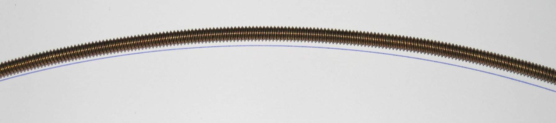
It is easy to see that the bolt has too much or too little curve against the template. You’ll need a bolt long enough to run for the tracking time you want plus extra for the thickness of the top and bottom board, gearnut thickness plus other hardware. Don’t use the ends of the rod which probably aren’t very true to the curve but just cut out the middle section of the rod truest to the template. I was shooting for 2 hours of tracking but ended up with 1 hour and 45 minutes. In reality I don’t need so much tracking time since the tracker is very easily and quickly reset.
Once I had my bent bolt I measured and drilled a hole 10.95 inches from the hinge pivot center through both boards. Why 10.95 inches? Even though steppers can be adjusted for a wide range of speeds I thought it would be convenient to be able to measure the speed by counting a certain number of revolutions to be an even number of minutes (for setting the right speed). In my case a revolution of 1.15 rpm gives 23 rotations in 20 minutes which gives a radius of:
1436 * 1.15 / 24 thi / Pi / 2 = 10.95 in.
The hole in each board is straight up and down instead of curving path through the wood.
Exaggerated Curve Path of Bolt
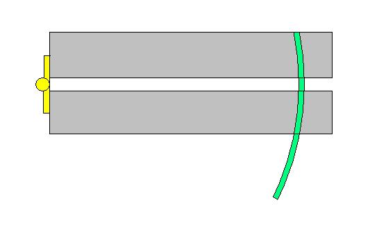
This causes two small problems.
On the top board when you attach the curve bolt and tighten it down with nuts on each side of the board it will miss the hole drilled on the other board as shown.
Once tightened down you simply bend the bolt at the nut on the top board so that the other end goes though the hole in the bottom board. The second problem is that the curve bolt traces a curved path through the bottom board that will cause binding. To fix this problem the hole in the bottom board (if not relieve cut as I did) should be counter-bored on the back side to about 1/8 inches from the top. The counter-bore should be large enough that the curve bolt doesn’t rub the wood there. Finally the hole in the bottom board should be only slightly larger than the bolt diameter. Be sure to use one washer under the gearnut too. Done correctly the curve bolt will swing freely though the bottom board with no noise or binding.
I next drilled a hole for my spur gear to protrude through and drilled holes for the motor. I used a threaded brass insert on the bottom board for attaching it to a tripod. Also I bought a camera swivel adaptor for $30 and attached it to the top board using a 1.5 inch spacer to allow the camera to swing through any position. I mounted a battery holder and the driver board underneath to keep things compact. The last thing to do with a stepper drive is to calibrate the motor speed. My gearnut should rotate at 1.15 rev per minute or 23 revs. in 20 minutes. It helps to have a DMM reading the frequency of the board output. I put a black dot on the gearnut for timing the revolutions.
A motor may have enough of torque that when the gearnut bottoms out and is stopped by a nut a plastic gear may be damaged by a high torque motor. On mine the motor just stalls out with no damage but a clock motor might have too much torque. With steppers you can add resistors to each field coil to reduce the torque and save power as well.
The Gearnut
Don’t be cheap, use a good quality machined nut on the gearnut, longer is better but not too long that it binds on the curve. A brass threaded insert works well or a well machined plug pressed into the gear center. Mine is a steel plug.
Finder
It’s handy to have a means of aligning the tracker to the pole. You can always sight along the hinges at the pole but it is more convenient to have a finder. Some use a finder scope mounted on the top board. I will use a Howie Glatter green laser laid in a V-block on the board. In either case you need to align the finder or laser to the hinge axis by aiming at a distant target and swinging the top board through 180 degrees. The finder or laser should swing though a similar radius when properly aligned.
Resetting
When the gearnut reaches the end of its travel the curve bolt must be reset. It couldn’t be simpler. You simply lift up the top board which disengages the gearnut and you simply spin it back to the start, it takes only seconds and you’re ready to go again.
References:
Sky & Telescope magazine Oct. 1980 Gleanings “Some Experiments with Curved Bolt Drives” by Ed Jones (inventor of curved bolt)
Sky & Telescope magazine June 2007 “A Tracking Platform for Astrophotography” by Gary Seronik also http://www.garyseronik.com/?q=node/52
